


Before some years I started beeing interested in smart home and especially in creating it by myself ![]() My first project was a tutorial to build a temperature sensor which sends the data to my raspberry gateway via 433MHz. As these tutorial were quite old I had to exchange some hard and software to make it work but it was a nice challenge. End of 2018 I then thought that it might be nice to enhance the sensor by measuring volatile organic compounds and CO2. Some could say that I could buy an existing sensor but you know, ... that wouldn't be fun
My first project was a tutorial to build a temperature sensor which sends the data to my raspberry gateway via 433MHz. As these tutorial were quite old I had to exchange some hard and software to make it work but it was a nice challenge. End of 2018 I then thought that it might be nice to enhance the sensor by measuring volatile organic compounds and CO2. Some could say that I could buy an existing sensor but you know, ... that wouldn't be fun ![]()
Measuring volatile compounds
After some research I decided to choose CCS811 chip for measuring the total volatile organic compounds (tVOC) because it was quite cheap and it can operate on 2.7V+, which was necessary because my existing setup is supplied by 3 AAA batteries. The chip can also calculate the estimated co2 value (eCO2) based on the tVOC. So I bought a CJMCU-8118 breakout on Amazon for around 15€ but you can buy it cheaper on alibaba or Ebay. I just like that Amazon doesn't make trouble with returns and problem solving.
Once the chip arrived I started to connect it to the raspberry pi and made a 48 hours burn in reading which is required by the chip. I were super suprised that everything worked out immediatly and I got some reasonable numbers which changed after some time but I planned to fix that later.
Finding the libraries
From my previous sensor I already had the libraries for the DHT22 temperature sensor and for the RFM69 433MHz transciver module. The important thing about the library for the FM69 module is that it comes with a lightwight custom implementation for SPI. The reason is that the RFM69 transceiver works with SPI and the common SPI library doesn't support the ATtiny84 micro controller I am using.
Coming to the library for the CCS811 I first tried the library from Maarten Pennings but switched to the Adafruit_CCS811 (GitHub) because the other gave me super wrong values. While choosing the library I learned about the I2C Bus (I'm a big newbie to this whole topic) and recognized pretty soon that the SDA and SCL pins of the ATtiny are the same as MOSI and MISO whose were already used by the SPI connection to the RFM69 module. I just thought what the hell, may it be possible to just use other pins? Indeed it is but only with software I2C which is different to the hardware variant and a bit slower. Googling around for some seconds and I found the library SoftI2CMaster (GitHub). It comes with a SoftWire class having the same interface as the Wire.h API. Using this software I2C allowed me to use different pins for SDA and SCL. Yay ![]()
 Planning the wiring
Now where I found the libraries to use I thought about the wiring. I were looking for a tool to plan how my perfored plate should be wired and I found Fritzing. It is actually quite nice and simple but it is not easy to find a proper components which matches those I have. After I had a rough plan the result looked like this but changed afterwards slightly again ==>
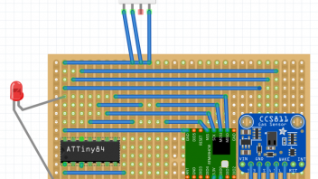
My final working prototype were looking like this
The picture shows:
- a socket for the ATtiny84 wired to the raspberry pi to burn it with arduino and avrdude via linuxgpio
- a RFM69 module wired on the breadboard to the raspberry pi as receiver
- the sensor prototype including an ATtiny84, RFM69, DHT22, CCS811 and ... a LED ![]()
At some point the LED were replaced by one wire for sending logs from my sensor to the arduino ide via SoftwareSerial. For the final prototype I had to remove SoftwareSerial again as it added around 2K of program size.
Other challenges
After putting everything together I got problems with the limited flash size of 8K on my ATtiny84. The number of 5 different libraries for one sensor were slightly to much ![]() I luckily could fix this by throwing away some obsolete exception handlers, prints and other code of the libraries which wouldn't make sense anyways.
I luckily could fix this by throwing away some obsolete exception handlers, prints and other code of the libraries which wouldn't make sense anyways.
To shrink the programm even more I also had to use a different data schema for sending than creating a string to parse. So I decided to have a fixed length of 10 bytes to send, where every value uses 2 bytes. That reduced the size also drastically because sprintf or itoa are quite big.
At the end I managed it to burn the program of 7806 bytes to my ATtiny84 and could receive the data in my custom sensor of the Home Assistant server running on my raspberry pi.
The last problem I'm currently facing (and what I mentioned before) is that I'm getting sometimes strange and jumping values as you can see on the following picture and I currently have no clue why ![]()
The result in home assistant looks like this:
I'm thinking about creating a tutorial but I guess that might take a while ![]()
Beside the tutorial my next plan is to create a USB to USB adapter which I can control with Google Assitant at the end. Using this I can toggle electronic devices like LED strips conntected to my TV's or Monitors to have a fancy light. Also I plan to create a 433MHz based controller to my Ikea Ansluta (light in the kitchen) and connect this via Home Assitant to Google Assistant. Yay so many assistants and still we have a bunch of things to do on our own ![]()
I hope you enjoyed reading but if not tell me what I can improve ![]()
Best
FragSalat